|
explosion proof VFD,HazLoc softstarter, motor soft starter, vector control variable speed drive (VSD, variable frequency drive, AC drive, inverter), reactor, sine wave filters, power electronics: quality as ABB, Siemens.
|
Cascade control of V&T EcoDriveCN® AC variable frequency drives (VFDs)
Here we introduce three kinds of the most commonly used cascade control methods for V&T Technologies Co.,Ltd. EcoDriveCN® AC variable frequency drives (VFDs): cascade control 1, cascade control 2, and cascade control 3.
Cascade control 1 is the cascade control with analog signal cascade.
Cascade control 2 is the cascade control with communication.
Cascade control 3 is using the method of high speed pulse input/output: DI/DO.
Application areas:
Cascade control 1: need two or more AC variable frequency drives to cascade control
Cascade control 2: need two AC variable frequency drives to cascade control
Cascade control 3: need two or more AC variable frequency drives to cascade control
1. Cascade control 1 (analog signal through analog terminals):
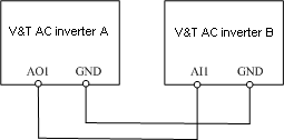
Wiring diagram:

System scheme:
We introduce cascade control with analog input/output terminals. Refer to the figure above for wiring. Several AC variable frequency drives (VFDs) can be cascade connected.
AC variable frequency drive (VFD) B can run velocity-tracking to AC variable frequency drive (VFD) A. AC variable frequency drive (VFD) A output the current running frequency through the terminal AO. AC variable frequency drive (VFD) B input the current frequency-setting instruction through the terminal AI. Note that it's input and output of analog voltage, should put the connection wiring between the terminal AO of VFD A and the terminal AI of VFD B to the correct position.
Setting of functional code
Let's take the given terminals of wiring diagram for example.
The function code of achieving the control above should be set as:
AC variable frequency drive (VFD) A: P7.03 = 48. It's factory default.
AC variable frequency drive (VFD) B: P0.04 = 1, setting the frequency with analog of the terminal AI1.
Because there's circuit error during the process of input and output of analog voltage for both drive A and drive B, the errors exist for the running frequency of drive A and drive B, the curve of analog of the terminal AI1 of drive B can be corrected.
For example, we want to set the operating frequency of drive A and B as 50Hz. But the given shutdown frequency of drive B is 0.43, the operating frequency is 47.5Hz. When drive B is shutdown, and drive A is shutdown, note that the analog voltage of terminal AI1 from the operation panel of drive B is 0.08V. When drive B is shutdown, and drive A is running, note that the analog voltage of terminal AI1 from the operation panel of drive B is 9.5V.
Referring to group P6 of functional code of the manual (or calculating via the drive interfaced of parameters setting), we get the result that the functional code of drive B is: P6.00=4440, P6.01=0.8, P6.02=0, P6.03=95, P6.04=50. Set the functional code of drive B as the result above, drive A and drive B can get the synchronous running frequency.
Attention
The jump of terminal AO and AI should be connected to the correct position
During the correction for parameters curve, if the operating frequency of drive B is not synchronous enough, the parameters P6.01 and P6.03 can be fine tuned with the curve correction function.
2. Cascade control 2 (through RS485 communication port)
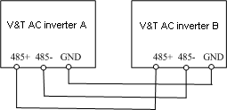
Wiring diagram

System scheme
Master and slave communication cascade control method is introduced here. Please refer to the wiring diagram above. Set the VFD A is the master drive. VFD B is the slave one. And the write position of functional code of the slave drive B is set as P0.05.
Setting of functional code
The functional codes are set according the introduction above:
VFD A: P0.04 = 2, P0.05 = 0.
VFD B: P0.04 = 0, P0.05 = 0.
After setting, master and slave communication cascade control is available. Through changing the frequency setting P0.05 of master drive A, that frequency setting of the slave drive B is changed according to A. And there's no error of frequency setting.
Attention
Set the parameter P0.06. It can set the correction factor of the slave drive accepting the setting of master drive. The setting of slave drive = P0.06 * the setting of master drive.
3. Cascade control 3 (with pulse input/output terminals of frequency inverters)
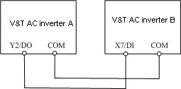
Wiring diagram

System scheme
Here cascade control with pulse frequency setting is introduced. Refer to the diagram above for wiring. Drive A is pulse output. The output frequency corresponds to one pulse frequency. Drive B receive the pulse signal, gives the operating frequency of drive B with the pulse frequency.
Setting of functional code
Drive A: P7.01 = 48
Drive B: P0.04 = 4, P5.06 = 5.
After inputting the functional code of AC variable frequency drives, change the parameter of frequency setting P0.05 of VFD A, the given frequency of VFD B is changed synchronously. The synchronization is relatively good.
Attention
This method can achieve cascade control with less than 0.0.15% error.
Can get the proportional relationship between the frequencies of drive A and drive B. For example, if the given frequency Fa of VFD A is 50 Hz, the frequency Fb of VFD B after the signal of pulse frequency is 10 Hz. That means Fa = K * Fb. Here K = 5.
We can set the max output pulse frequency of Y2/DO of VFD A P7.10 = 10Hz, K = P5.10 / P7.10, the different parameters can be set according to the different demands.


 Photo Gallery |CE certificate |superb components
 |
| © 2016 V&T All rights reserved. |
 Our Expertise Is Your Guarantee!Leading manufacturer and supplier industrial automation, motor control, motion control and energy efficiency. |